User Manual liteServer Ex.micro
Safety instructions
Attention
- Absolutely observe the installation's safety directions of the T20 liteServer series!
- Observe the instructions stated on the type plate!
- The luminaire is not suitable for use in zone 0 and 20!
- Temperature class and explosion group must be absolutely adhered to!
- The specified temperatures have to be observed!
- The customer is not allowed to make any alterations of the luminaire.
- The luminaire must be operated in a proper and sound condition and only in the way intended.
- Repairs may only be carried out by using original parts from the manufacturer. Repairs which affect explosion protection may only be carried out in accordance with the nationally applied regulations and exclusively by the manufacturer.
- When installing the liteServer adhere to the requirements of the EN/IEC 60079-14.
Warnings
WARNING:
DO NOT OPEN IN POTENTIALLY EXPLOSIVE ATMOSPHERES
Observe the safety instructions in the installation guide!
--------------------------------------------------------------------------------------------------------
ВНИМАНИЕ:
НЕ ОТКРЫВАТЬ в потенциально взрывоопасных средах
Соблюдайте инструкции по технике безопасности в руководстве по установке!
---------------------------------------------------------------------------------------------------------
AVERTISSEMENT:
NE PAS OUVRIR EN ATMOSPHÈRES EXPLOSIBLES
Respectez les consignes de sécurité dans le guide d'installation!
---------------------------------------------------------------------------------------------------------
AVISO:
NÃO ABRIR DENTRO DE UMA ÁREA COM PERIGO DE EXPLOSÃO
Observar as instruções de segurança nas instruções de instalação!
---------------------------------------------------------------------------------------------------------
Attention!
The sight glass must not be directly covered by foreign objects. The light must be able to leave the optics of the protective housing unhindered. Regular cleaning intervals of the sight glass should be observed in order to avoid adhesion and dust deposits.
Risk of burns from hot surfaces (≤80°C)!
Do not stare into the direct beam. Danger of impairment of vision due to high exposure to light!
Technical data
Explosion protection
| Identification marks acc. to Directive 2014/34/EU |
Ex II 2G (zone 1 and 2) |
| Ex II 2D (zone 21 and 22) | |
| Ex I M2 (only for MINING models) | |
| Explosion protection (gas) | Ex db IIC T5 Gb |
| Explosion protection (dust) | Ex tb IIIC T95°C Db |
| Ex db I Mb (only for MINING models) | |
| Protection level | IP 66/68 (IEC /EN 60529) |
| Transport/ storage temperature | 0°C…+70°C (non-condensing) |
| Ambient temperature (EX) | -30°C…+50°C |
| Certification | |
| EU type approval certificate | TÜV 21 ATEX 8696X (2021) |
| IECEx Cert. of Conformity | TUR 22.0076X (2022) |
| UKEX Certificate | TÜV 24 UKEX 7178X (2024) |
Model variants
Ex product name | Model variants | Article no. | |||||
|---|---|---|---|---|---|---|---|
1) | 2) Type
| 3) Housing (combination)
| 4) Temp. range | 5) Cable length [m] cable type | 6) Termination | Link to digital type plate | |
liteServer Ex.micro. | 24.WL90 |
T20-
|
VA0.1.K1.BOR-
|
L.N-
|
005.1-
|
K
| |
24.IR90 | T20- | VA0.1.K1.BOR- | L.N- | 005.1- | K | 24060118 | |
24.WL90 | T20- | VA0.1.K1.BOR- | L.N- | 005.1A- | K | 24060128 | |
24.IR90 | T20- | VA0.1.K1.BOR- | L.N- | 005.1A- | K | 24060130 | |
Description:
- liteServer Ex.micro.24.XX90 = Funktional description of the liteServer Series (technical data/ specification of the individual LED module)
liteServer Ex.micro.24.XX90 = ultracompact luminaire
liteServer Ex.micro.24.XX90 = 24V power supply
liteServer Ex.micro.24.XX90 = WL = white light; IR = infrared light
liteServer Ex.micro.24.XX90 = 90° beam angle - T20 = SAMCON Production- type 20 (ex-proof luminaire)
- VA0.1.K1.BOR = Ex-d housing (stainless steel 1.4404) with smallest diameter ØVA0=48mm)
VA0.1.K1.BOR = VA0.1 housing with short body lenght (LR = 127mm)
VA0.1.K1.BOR = K1 cablel- gland flange
VA0.1.K1.BOR = Borosilicate sight glass DIN7080 (standard) - L.N = High temperature (Tamb < +50°C)
L.N = low temperatures (Tamb > -30°C) - 005.1 = Length of the connection line in meter at delivery; 5m is the standard cable length, max. cable length is: 005...100 [m]
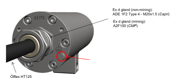
005.1 = Ölflex heat cable
005.1A = Ölflex heat cableand gland with mining certification - K = Terminal strip- termination (standard)
Electrical parameters
Power supply of the luminaire:
Voltage supply (WL): 24 VDC +/- 3 VDC
Voltage supply (IR): 24 VDC +/- 3 VDC
Maximum power consumption (WL): 12.9 W @ 24 VDC
Maximum power consumption (IR): 12.7 W @ 24 VDC
Connection cable
ÖLFLEX HEAT 125 MC
Electron beam cross-linked cables for increased application requirements; connecting cable
Outer diameter: 6.8mm
Conductor design: 3G0.75; 3x0.75mm2 (ø=1.4mm), fine-wired tinned Cu-strands acc. IEC 60228 or VDE 295
Bending radius: 15 x outer diameter at installation; 4 x outer diameter after installation
Temperature range: -35°C ... +120°C (at point of installation); -55°C ... +125°C (fixed installed)
Outer sheath/characteristics: Electron beam cross-linked, based on polyolefin copolymer, black, halogen free, flame resistant (EN 60332-1-2), UV and oil resistant
Appropriate cables & cable glands:
for this watch the following video-tutorial or the informations on the cable-page.
Attention!
- Cables and wires must comply with the requirements of the IEC 60079-0/1/7 & 14.
- The supply line must have a sufficient cross-section. The cable protection must comply with national and international regulations.
Cable glands
Ex d gland (non-mining)
Ex-d gland ADE 1F2 Type 4 - M20x1.5 (Capri)
The cable-cable gland combination has been tested with the following values:
Static pressure resistance: < 26 bar
Longitudinal tightness: acc. to IEC/EN 60079-14 Appendix E.
Test reports you can find in the Downloads of the product page.
Gland with mining certification
Ex-d gland for mining A2F100 (CMP)
The cable-cable gland combination has been tested with the following values:
Static pressure resistance: < 60 bar
Longitudinal tightness: acc. to IEC/EN 60079-14 Appendix E.
Test reports you can find in the Downloads of the product page.
Other technical data
Permissible ambient temperature: -30°C ... +50°C
Protection class as per EN 60529/IEC 529: IP66/68 (test conditions 30min/8m water column)
Housing material: Stainless steel mat. no.: 1.4404
Weight: ca. 1.4kg
Dimensions: 127mm x 65mm x 48mm
LED illumination
Information to liteServer Ex.micro
White light LED
A neutral white high-power COB LED with a nominal power of 12.5 W is used in this device as a radiation source for visible light. The COB LED is characterized by the following technical properties:
LED Type: COB-LED (InGaN), single phosphor dot, non-matrix arranged, divergent, non-focusing
Power consumption: 12.5W
Max. power consumption: 12.9W@24VDC
Color rendering: 440nm to 690nm
Color temperature: 5000K
Luminous flux: 1930lm
Beam angle: 90°
Dimensions (ØxH): 28 x 2.4 mm
IR LED
A SMD IR-LED with a radiance of 4120 mW is used in this device as a radiation source for visible light. The IR LED is characterized by the following technical properties:
LED Type: High Power 12W IR SMD-LED
Max. power consumption: 12.7W
Infrared centroid wavelength: 850nm
Radiation intensity (IR850): 4120mW
Beam angle: 90°
Operating hours: 50000h
Attention!
Infrared radiation may emanate from this product. Do not look directly at the operatimg lamp.
Illumination tests
The external illumination in combination with the ExCam IPM1137 ensures that you get a good image up to an object distance of 30.0m. Even at a distance of 60m, the light intensity is sufficient to be able to recognize an object in the field of vision. See the tests on the illumination of the ExCam IPM1137-LE in the Eleonore Stollen Asslar.
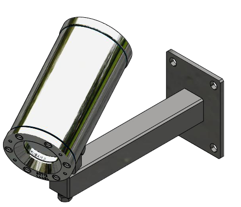
Mounting
Attachment with the Wall mount Bracket
Electrical Connection
- May only be carried out by qualified personnel!
- Ground the housing via PA-connection!
- Cabels have to be layed protected, observe bending radius!
- Electrical work inside the pressure resistant enclosure by the user are not authorized!
Connection and protection
Attention
- No reverse polarity protection! It is essential to ensure the correct polarity when making the electrical connection!
- Use only terminals approved by SAMCON.
Cable termination
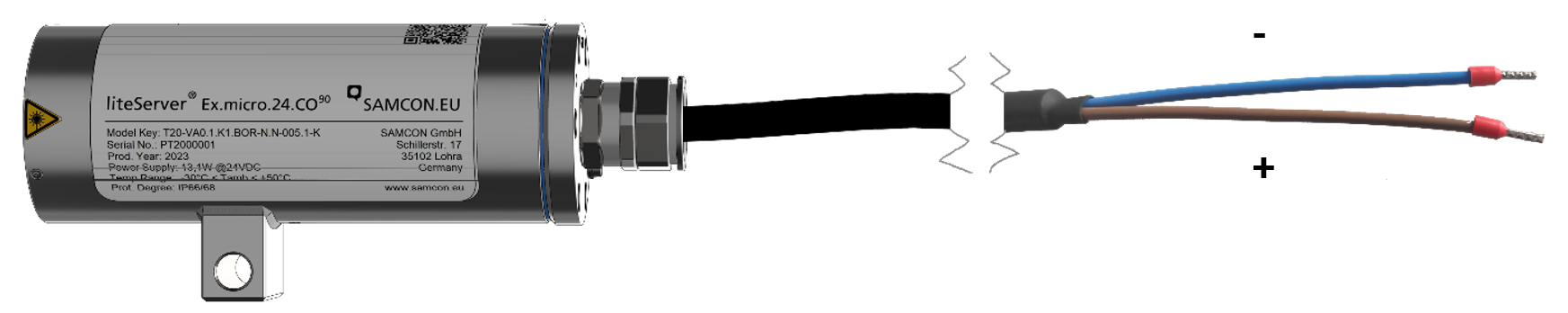
Via the black cable the illuminant is supplied with voltage. The power supply has to be done via the brown (BR) as well as the blue (BU) connection strand.
Potential | Color (IEC 60757) | Potential level | Profile | Remarks |
DC+ | BR | +24 V DC | 0.75 mm² | AWG22, fine stranded wire |
DC GND- | BU | 0 V DC / GND | 0.75 mm² | AWG22, fine stranded wire |
The dimensioning of the equipment or the supply protection depends on:
- cable length
- national regulations
The following safety recommendations may serve as a basis:
Supplied power | Length system cable | Recommended protection | Comments |
24 V DC | < 100 m | 800 mA - mT | In case the transmission range exceeds 100 m and it is intended to supply the luminaire with 24 V DC, please make sure to use an adjustable power supply in order to compensate voltage drops |
The release current of the protection has to be less than the maximum short-circuit current of the power supply (switch-mode power supply)!
Test prior to switching on voltage
Attention
- Prior to commissioning, all tests as indicated by the national regulations have to be executed. In addition, it is mandatory that the proper functioning of the operating device in accordance with this user manual and all other applicable regulation has been executed.
- Incorrect installation and operation of the liteServer may lead to a loss of warranty!
- If possible, carry out initial commissioning when the outside temperature is above 0°C to prevent condensation inside the housing.
Exchanging the illuminant / LED block
The illuminant should only be exchanged if it is defect. It must be replaced by an original spare part of the same model. In this special case it is allowed and necessary to open the Ex d housing. All required steps are described in this user manual; the descriptions stated in the T20 liteServer® Series Ex installation manual have to be observed!
Perhaps our video will help you: "Replacing the illuminant of liteServer Ex.micro"
Important!
- MAY NOT BE OPENED IN HAZARD AREAS
- Depending on classification of hazard areas, it is imperative to obtain a work approval first!
- Prevent explosive atmosphere!
- Do not damage the thread surface of the flame-proof gap and the housing seals!
Opening the pressure–resistant housing is only allowed to replace a defect LED. Afterwards, the housing has to be closed explosion-proof again! The steps below have to be followed very carefully.
Opening the luminaire housing
For opening the liteServer®’s pressure-resistant stainless steel housing T07 VA0.1.K1.BOR, it is mandatory to follow the step-by-step instructions as stated in the T20 Ex installation manual!
Loosen the six M3 cylinder-head hexagon screws (DIN 912/ ISO 4762) together with their spring rings (DIN 127A) on the rear side of the cable and power supply flange. Caution: do not touch the screw threads with your skin or clothes! On the threads, there is LOCTITE® 243™ (chemical basis is dimethacrylate ester) applied to prevent the bolted connection from unintentional loosening because of impacts and vibrations.
Carefully pull out the cable and supply flange to the rear, as straight as possible. Because of negative pressure, it may be difficult to remove the flange. The cylindrical clearance fit (H8f7 - DIN ISO 286) of the housing body and flange may not be tilted! Risk of damage to the flame-proof gap (DIN EN 60079-1:2012)!
Caution: do not touch the cylindrical fit surface with your skin or clothes! On the surface, there is oil lubricating paste to protect the surface against fretting corrosion and mechanical stresses.
When you open the housing, pay attention that you do not damage the GYLON® flat seal (blue, RAL5012) and do not make it dirty! The flat gasket is loosely attached to the cable and power supply flange. It is fixed only by the bolted connections!
Pull out the luminaire carefully and pay attention not to clamp the cables.

Attention!
Beware not to damage the surface of bore hole and shaft (fit) at the flame proof gap preventing the transmission of ignition.
Please make sure not to damage housing sealings and to keep them clean.
Exchanging the illuminant
To replace the LED-block the 2 grub screws on the side must be carefully loosened. The LED block is plugged in and can easily be removed after loosening the grub screws. Seperate it at the plug contacts.

Insert the plug of the new LED replacement block into the connection socket oft he housing flange. Make sure that the plug contacts and contact surface of the aluminium heat sink are clean and undamaged. After successfully replacing the LED block, the grub screws must be tightened again. Only use new, original grub screws. Tightening torque is 1.0 Nm! Loctite 243 may be used for screw locking.

When touching electrical components, potential equalization (grounding of the body) has to be observed (ESD clothing, PE wristband etc.)!
When closing the housing, the cable routing has to be observed! In order to avoid collisions and mechanical strain within the closed housing as well as to observe the necessary bending radius, the cable has to be looped.
Closing of the pressure-resistant housing
For closing the housing, proceed in reverse order as when opening. Use exclusively original screws included in the supply. Materials of bolted connections are identical to the pressure-resistant stainless steel housing (standard material no. 1.4404 AISI316L). Check whether the threaded holes are undamaged and clean. Before closing, it is also absolutely imperative to check the flame-proof gap (circular cylindrical fit).
Attention!
If any mechanical damages occurred to the fitting gap, it is no longer allowed to use the housing!
Attention!
Do not lock-in any foreign objects in the housing.
Attention!
Insert the flange to reach the end position, in order to ensure ignition protection and the protection level (IP) of the housing.
Dismantled screw locks (spring washers DIN 127A) must be used again. The GYLON® gasket must be used in undamaged condition, according to the flange hole pattern, and placed between the flange and the hull. The lateral position of the flat surface / contact surface is arbitrary. If, when closing the housing, you see that the surface of the fitting gap is dirty or insufficiently lubricated, clean it with a clean cloth and de-grease it with a suitable cleaning agent. Then re-grease it with lubricant suitable for this specific application (e.g., Molykote® P-40 gel for standard applications or special grease OKS 403 in the event of heavy seawater influence).
Cylinder-head bolts for explosion-proof connection of the luminaire body with the flange component must always be tightened at a 1.2 Nm torque - crosswise and evenly! Use Loctite.


