User Manual ExCam miniTube IP
Safety instructions
Attention
- Absolutely observe the installation's safety directions of the T08 ExCam series!
- Observe the instructions stated on the type plate!
- The camera is not suitable for use in zone 0 and 20!
- Temperature class and explosion group must be absolutely adhered to!
- The specified temperatures have to be observed!
- The customer is not allowed to make any alterations of the camera.
- The camera must be operated in a proper and sound condition and only in the way intended.
- Repairs may only be carried out by using original parts from the manufacturer. Repairs which affect explosion protection may only be carried out in accordance with the nationally applied regulations and exclusively by the manufacturer.
- When installing the ExCam adhere to the requirements of the EN/IEC 60079-14.
Warnings
WARNING:
DO NOT OPEN IN POTENTIALLY EXPLOSIVE ATMOSPHERES
Observe the safety instructions in the installation guide!
--------------------------------------------------------------------------------------------------------
ВНИМАНИЕ:
НЕ ОТКРЫВАТЬ в потенциально взрывоопасных средах
Соблюдайте инструкции по технике безопасности в руководстве по установке!
---------------------------------------------------------------------------------------------------------
AVERTISSEMENT:
NE PAS OUVRIR EN ATMOSPHÈRES EXPLOSIBLES
Respectez les consignes de sécurité dans le guide d'installation!
---------------------------------------------------------------------------------------------------------
AVISO:
NÃO ABRIR DENTRO DE UMA ÁREA COM PERIGO DE EXPLOSÃO
Observar as instruções de segurança nas instruções de instalação!
Technical data
Explosion protection
| Identification marks acc. to Directive 2014/34/EU |
Ex II 2G (zone 1 and 2) |
| Ex II 2D (zone 21 and 22) | |
| Ex I M2 (only for models with armoured cable and plug termination) | |
| Explosion protection (gas) | Ex db IIC T6 Gb |
| Explosion protection (dust) | Ex tb IIIC T80°C Db |
| Explosion protection (mining) | Ex db I Mb (only for models with armoured cable and plug termination) |
| Protection level | IP 66/68 (IEC /EN 60529) |
| Ambient temperature (EX) | -30°C…+50°C |
| Named testing laboratory | TÜV Rheinland (number 0035) |
| EU type approval certificate | TÜV 18 ATEX 8218X (2018) |
| IECEx Cert. of Conformity | TUR 18.0023X (2018) |
| INMETRO-Certificate | TÜV 23.0363X (2023) |
| EAC-Ex TUR Report | TC RU C-DE.HA65.B.01652/22 |
Model variants
Models for different temperature ranges, with different termination and 3 lenses for selection
Ex product name | Model variants | Artikelnr. | ||||
|---|---|---|---|---|---|---|
1) | 2) Type
| 3) Housing-(combination) | 4) Temp.-range | 5) Cable length [m] cable type | 6) Termination | Link to digital type plate |
ExCam miniTube IP | T08- | VA1.2.K1.BOR- | N.N- | 005.N- | P | |
T08- | VA1.2.K1.BOR- | N.N- | 005.N- | T | 22070527 | |
T08- | VA1.2.K1.BOR- | N.N- | 005.A- | P | 22070529 | |
T08- | VA1.2.K1.BOR- | N.N- | 005.A- | T | 22070530 | |
Description:
- ExCam miniTube IP = Functional camera description of the ExCam Series (technical data/ specification of the individual camera module)
- T08 = SAMCON Production- type 08
- VA1.2.K1.BOR = T07 Ex-d housing (stainless steel 1.4404) with small diameter (ØVA1=79mm)
VA1.2.K1.BOR = T07 VA1.2 housing with medium body lenght (LR = 158mm)
VA1.2.K1.BOR = K1 cablel- gland flange
VA1.2.K1.BOR = Borosilicate sight glass DIN7080 (standard, for video cameras within visible spectral range: λ = 350...2000 [nm] and fotografic infrared range NIR, not suitable for thermografic applications (MIR/ FIR), for cameras without wiper - N.N = Normal temperature range (Tamb < +50°C)
N.N = No PTC heater integrated (Tamb > -30°C) - 005.N = Length of the connection line in meter at delivery; 5m is the standard cable length, max. cable length is: 005...100 [m]
005.N = Non armoured cable
005.A = Armoured cable - P = Plug- termination (standard) CAT6, RJ-45 network plug (heavy duty), AWG 26-22, contact assignment acc. to specification EIA/TIA-568B
T = Terminal box- termination (optional) 4 x PoE Mode A connection (camera PoE) (see electrical connection)
Electrical parameters
Power supply of the camera (PoE):
Voltage supply: PoE, IEEE 802.3af type1 class 2
Reference voltage: +12 V DC
Maximum power consumption: 4.4 W
Typical power consumption: 3.0 W
Connection cables
Appropriate cables & cable glands:
for this watch the following video-tutorial or the informations on the cable-page.
Attention!
- Cables and wires must comply with the requirements of the IEC 60079-0/1/7 & 14.
- The supply line must have a sufficient cross-section. The cable protection must comply with national and international regulations.
Video-technical characteristics
Other technical data
Permissible ambient temperature: -30°C ... +50°C
Protection class as per EN 60529/IEC 529: IP66/68 (test conditions 24h/3m water column at 5°C)
Housing material: Stainless steel mat. no.: 1.4404
Weight: ca. 2.6kg
Dimensions: D79mm x 158 mm
Mounting
Attachment with the Wall mount Bracket

Electrical Connection
- May only be carried out by qualified personnel!
- Ground the housing via PA-connection!
- Cabels have to be layed protected, observe bending radius!
- Electrical work inside the pressure resistant enclosure by the user are not authorized!
Terminal box Assignment
Attention
- Never open Ex-e terminal box under voltage!
- Adhere to the international installation regulations for connection chambers with increased safety (Ex-e).
- Adhere to attached seperate User Manual for the ex-e terminal box.
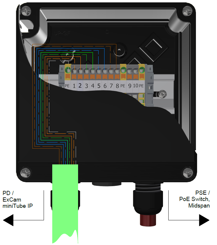
Connection work at the terminal box
Plug Assignment
Plug assignment RJ45 plug acc. to EIA/TIA 568B
Connection work with plug

Attention!
- Use appropriate RJ45 plugs! Check the cable shielding, cross-section and the outside diameter!
- It is imperative to ensure a correct routing of the individual wires acc. to EIA/TIA-568B.
- Finally, check your network installation with a Class-D Link test.
Direct routing from the ExTB-3 into the safe area

Routing via ExConnection Rail (optional accessories)

Tests prior to switching on voltage
Attention!
- Prior to starting the device, perform all tests as indicated by the national regulations. Furthermore, check the correct function and installation of the device in accordance with this User Manual and other applicable regulations.
- Incorrect installation or operation of the camera may lead to a loss of warranty!
- Do not switch on the camera at temperatures below 0°C!
Working inside the camera housing (Ex-d)
Reason for opening the housing:
- Hardware-reset
Important!
- Depending on classification of hazard areas, it is imperative to obtain a work approval first!
- Prevent explosive atmosphere!
- Do not damage the thread surface of the flame-proof gap and the housing seals!
Opening the pressure-resistant housing
Remove weather protection roof, if camera is equipped with one.
Loosen the eight screws on the rear side of the cable and power supply flange. Never open the front-side sight-glass flange.
Carefully pull out the cable and supply flange to the rear, as straight as possible. Because of negative pressure, it may be difficult to remove the flange. The cylindrical clearance fit (H8f7 - DIN ISO 286) of the camera body and flange may not be tilted! Risk of damage to the flame-proof gap (DIN EN 60079-1:2012)!


Attention!
The mounting adapter with the housing’s PTC heater, camera module and optics, as well as the temperature control, and (if applicable) auxiliary relays and terminal block are fixed on the cable and supply flange. Dealing with these components, too, you have to work very carefully and precisely in order to avoid canting and damage to the in-built components! Caution: do not touch the cylindrical fit surface with your skin or clothes! On the surface, there is oil lubricating paste to protect the surface against fretting corrosion and mechanical stresses. When you open the housing, pay attention that you do not damage the GYLON® flat seal (blue, RAL5012) and do not make it dirty! The flat gasket is loosely attached to the cable and power supply flange. It is fixed only by the bolted connections!
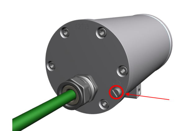
Hardware Reset
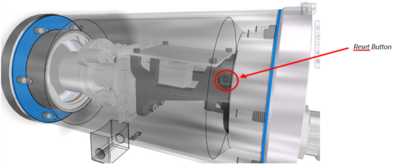
To set all the parameters of the ExCam miniTube IP (including the IP address) to default values, you should run a hardware reset. The parameters can be reset via the web interface or manually. If the camera placed in the network can no longer be reached or its state is uncontrollable, the reset should be performed manually. To do so, proceed as follows:
- Disconnect the camera installation module from the power supply.
- Press and hold the reset button (see the illustration below) and, at the same time, connect the system to the voltage supply (PoE).
- Hold the control button pressed for about some seconds.
- Release the control button. After about a minute, the ExCam miniTube IP will return to factory defaults. If there is a DHCP server in the network, the IP address will be the following: 192.168.1.10
- IP address and password can be redefined. If the hardware reset is not satisfactory or the network camera shows serious conflicts or does not work as usual (errors in the browser visualisation, frozen images, control commands no longer processed, slowing down of the system, etc.), it may be necessary to re-install the current firm-ware, or to install an update.
Closing of the pressure-resistant housing
For closing the housing, proceed in reverse order as when opening. Use exclusively original screws included in the supply. The cable and power-supply flange (K1) is fixed by 8 cylinder-head screws M4*0.7 (ISO metric right-turning) with 12 mm thread length (DIN 912/ ISO 4762, grade 6g). Materials of bolted connections are identical to the pressure-resistant stainless steel housing (standard material no. 1.4404 AISI316L). Check whether the threaded holes are undamaged and clean. Before closing, it is also absolutely imperative to check the flame-proof gap (circular cylindrical fit).
Attention!
If any mechanical damages occurred to the fitting gap, it is no longer allowed to use the housing!
Attention!
Do not lock-in any foreign objects in the housing.
Dismantled screw locks (spring washers DIN 127A) must be used again. The GYLON® gasket must be used in undamaged condition, according to the flange hole pattern, and placed between the flange and the hull. The lateral position of the flat surface / contact surface is arbitrary. If, when closing the housing, you see that the surface of the fitting gap is dirty or insufficiently lubricated, clean it with a clean cloth and de-grease it with a suitable cleaning agent. Then re-grease it with lubricant suitable for this specific application (e.g., Molykote® P-40 gel for standard applications or special grease OKS 403 in the event of heavy seawater influence).
Cylinder-head bolts for explosion-proof connection of the camera body with the flange component must always be tightened at a 3 Nm torque - crosswise and evenly! Use Loctite.
Commissioning, network access and visualization
The camera is configured via the device's own website, the video stream can be accessed via RTSP or you can integrate the camera into your video management system using the ONVIF protocol.
Network access
The camera obtains an IP address via DHCP. If there is no DHCP server on the network, the default IP address is 192.168.1.10
Default username: admin
Default password: admin
Without a DHCP server, please add multiple cameras to the network one after the other to avoid conflicts due to identical IP addresses.
To find out the IP address of the camera assigned via DHCP, you can display or assign it using the eneo Site Manager.
eneo Site Manager - Allocating IP address
Download the eneo Site Manager here:
https://eneo-security.com/en/eneo-site-manager.html
The eneo Site Manager automatically detects cameras present in the network and displays their IP addresses in a device list. The ExCam miniTube IP has the designation “ISM-72M2713W0A”.
If necessary, you can also assign a static IP address to the camera. To do this, select the camera in the list, right-click to open the context menu and then the network settings. De-activate the DHCP checkbox and set the desired IP address.
Web interface, configuration and control
Enter the camera's IP address in your web browser and open the web interface. By auto-matically redirecting to ... you may receive a message that the connection is not secure or private. Please confirm opening the website using the “Advanced” button.
Default username: admin
Default password: admin
The web interface is intuitive and offers a variety of configuration options. Detailed docu-mentation on the web interface can be found in the eneo operating instructions:
234669_en_short_man.pdf (eneo-security.com)
234669_en_man.pdf (eneo-security.com)
When delivered the ExCam miniTube IP is set to the applicable network frequency.
PAL = 50Hz (Europe) / NTSC = 60Hz (USA)
Visualization, RTSP video stream
The camera's video stream can be visualized via the following addresses:
RTSP
rtsp://<user>:<password>@<ip>:554/1/stream1
rtsp://<user>:<password>@<ip>:554/1/stream2
rtsp://<user>:<password>@<ip>:554/1/stream3
Example:
rtsp://admin:admin@192.168.1.10:554/1/stream1
JPG (Stream 3)
<ip>/cgi-bin/snapshot.jpg
MJPG (Stream 3)
<ip>/cgi-bin/jpegpush.cgi
ONVIF, VMS integration
The camera can be integrated into your video management system (VMS) via ONVIF Profile S and Profile T. We recommend AXIS Camera Station or ONVIF Device Manager for easy configuration.
Accessories


Other Accessories
Hinge attachement, Thermo isolator, Twin-adapter, SuperClamp-Mounting adapter